< View Blog
The Path to Zero Flap: Reinventing Optical Reliability for Scalable AI Clusters
As AI clusters have scaled so have the challenges with optical link flaps. Credo and Oracle have worked together to rethink and reimagine how to deliver much better network reliability with optical modules. This is the story of that journey, shared at the 2025 OCP Global Summit.
It was almost two years ago when Credo CEO Bill Brennan and his team began to realize that the back-end network reliability of AI clusters was the highest priority for customers. As AI clusters have scaled so have the challenges with optical link flaps. A single unstable optical link can trigger disruptive link flaps that derail AI training runs resulting in loss of time, resources, and money.
Steve Manley, senior principal network engineer at Oracle, knows first-hand the challenges with scaling AI systems and optical link flap issues, and has spent a lot of time thinking about it. Steve and Credo’s senior vice president of product, Don Barnetson, started a conversation about link flaps a year and a half ago.
“We love it when we hear from customers, when we hear pain points and then we can start collaborating together to talk about solutions,” said Bill.
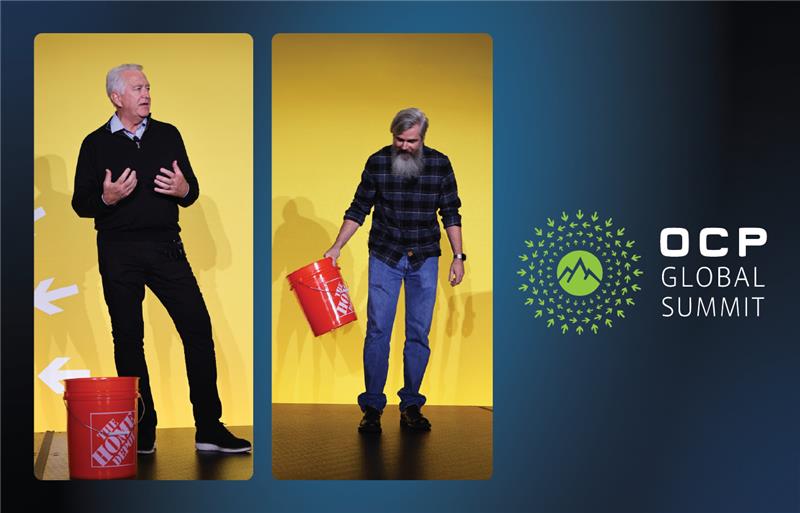
Since that initial discussion, Oracle and Credo have worked together to rethink and reimagine how to deliver much better network reliability with optical modules. That journey was shared by Bill and Steve at the 2025 OCP Global Summit Executive Session, “The Path to Zero Flap: Reinventing Optical Reliability for Scalable AI Clusters.”
The AI Scale Problem
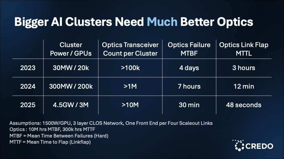
When Steve joined Oracle about three years ago, an AI cluster consuming approximately 3 megawatts (MW) of power was considered “big.” By the end of 2023, a “big” AI cluster was around 30 MW (about 20,000 GPUs). To put this into context, 30 MW is roughly the amount of energy needed to power a small town. By the end of 2024, 300 MW clusters—power consumption that is equal to a large city’s residential demand—were deemed “big.” Today, the industry is looking at 4.5 gigawatt (GW) clusters of about 3 million GPUs—enough energy to power 3-4 million homes in the U.S.
As AI clusters have grown significantly in size relative to GPU counts and power consumption over the past three years, so has the optical transceiver count per cluster. However, the mean time between optics failures (MTBF) and the optics mean time to flap (MTTF) have decreased significantly over the past three years. Failures scale with size as the probability of something going wrong multiplies across millions of optical devices.
“We have to do better,” said Steve. “The MTBF isn’t high enough and the time to flaps is the same problem.”
The Link Flap Issue
A link flap, as defined by Steve in the session, is an unexpected state transition on an optical link. There are a number of causes of optical flaps. These range from issues with the transceivers and its parts; thermal dependencies (the profiles of optics and lasers are some of the most sensitive electronics made to thermal variation); ESD damage from installation; assembly defects; firmware issues; optic interoperability issues between switches and NICs; and deployment velocity and hygiene when it comes to building out data centers quickly.
“You can’t put optics together in a pristine environment when you’re pouring concrete next to them,” said Steve. “And we don’t have the luxury of waiting for the buildings to look perfect before we bring the optics in. We have to go fast and faster.”
How link flaps manifest is critically important, Steve shared. He went on to further explain that challenges arise when an optical link has been damaged in a way that gives it a higher probability of failing later. If 100,000 of these links are then deployed into a fabric, then what is created is a population of links that flap. Every one of these links will flap at a different time. In aggregate, the links behave like a bunch of fast flapping links, and this can be very impactful to the Remote Direct Memory Access (RDMA) network that AI clusters are built on, and subsequently, its workloads.
Using the OSI model as a reference point, a link flap will affect the very lowest layer, L1. L1 instability can kick off a chain reaction in the networking system that can lead to workload job instability and checkpoint thrashing. If a workload has checkpoints, which is standard practice to mitigate a crash, the system will go back to that checkpoint. If the checkpoint is one hour, for example, and the cluster is running on 32,000 GPUs, that means that there are 32,000 compute hours potentially at risk of being lost or delayed and leading to potential lost revenue. The stress of link flaps on steady-state congestion can have widespread impact as the problem envelope scales with workload size.
“This problem gets worse the bigger it gets,” said Steve. “And we’re building geometrically. What wasn’t a problem with 2,000 nodes, when you go to 20,000, suddenly becomes a really big problem. So this is real.”
To countermeasure the issue of unstable fabric, Steve explained that accelerated fabric grooming takes place. This means shutting down a high number of optical links — even if there is just a suspicion that something is unstable.
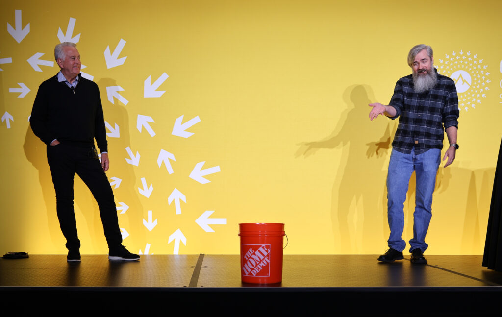
Steve continued, “So every fabric that has a problem or for a lot of them, I go have a look. And in the back of the data hall, I see these Home Depot buckets. And they’re full of optics. And the universal standard with the bucket of optics is that no one can tell me what’s wrong with any of the optics. And you can fit a couple hundred thousand dollars’ worth of optics in one of those buckets, but that’s not the real problem. The issue is that 800G optics are in pretty high demand right now and I’d rather them be in switches than in that bucket. And in order to keep them out of the bucket, I have to know they’re good. So we have to do better. Transceivers have enough compute on them that they can do better for us.”
Zero Flap Optics Solution: Making Optics Smarter
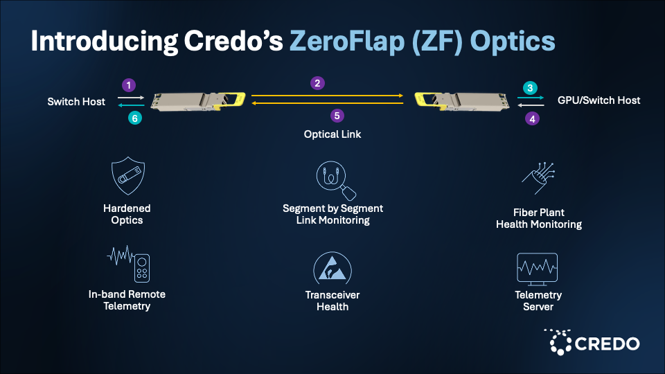
The first compute node that knows there is a problem with an optical link is the transceiver. The transceiver is made up of microprocessor cores that have access to all the data of the device, enabling it to make decisions. The Zero Flap Optics solution involves taking the optics performance and decentralizing it from the DSP. This provides complete visibility into link health on all tiers and enables the optics to talk to each other, providing information such as the serial number and the link status of its matched partner.
The Zero Flap Optics solution enables the network engineer to set parameters on link quality management, determine what link error behavior looks like, and receive information on which optic experienced the transient state. Zero Flap Optics can also help manage the fabric optics lifecycle and enable distributed and scalable link quality monitoring.
Essentially, Zero Flap Optics can serve as a “check engine light” for the transceiver, explained Steve. He continued, “I want it to tell me that something’s wrong and signal it.”
Credo’s Approach: Leveraging Credo PILOT Software
At the OCP Global Summit 2024, Credo introduced its ZeroFlap (ZF) active electrical cables (AECs) in direct response to a customer that had come to Credo with the goal of building a “zero flap” cluster. The customer was rearchitecting their server row from 18 racks to 6 racks through liquid cooling and power sourcing, enabling them to quadruple the density of their appliance racks. The customer had asked Credo to build 7-meter AEC cables with the goal of spanning the entire row in the rack and driving much better network reliability.
“They were using all optics previously,” said Bill. “And the message they gave us was that they were losing about 20 to 30% of their productivity—their uptime—because they were fighting link flaps constantly.”
Credo is taking the lessons and technology learned from its approach to ZF AECs and applying it to optics to address distances that go beyond seven meters.
“We have been thinking, how do we go up the stack, integrate at a higher level within the network and provide a massive amount of telemetry data to the network engineers,” continued Bill.
The approach to ZF Optics by Credo, like its approach with AECs, is first to harden the optical link. Bill explained that this involves taking customers’ gear with Credo’s optical solutions, placing the devices in a thermal chamber, and breaking them repetitively. Following root cause analysis of the equipment, the equipment is fixed, and Credo can add two to three orders of magnitude advantage to the optics solution that is delivered to the customer, creating operational margin.
Second, Credo’s approach is to give as much telemetry data as possible on the optical link at a DSP hardware level combined with PILOT firmware. This means collecting data real time, anytime and being able to present it. The data includes detailed information such as the eye height, signal-to-noise ratio (SNR), Pre-FEC bit error rate (BER), FEC histogram, multi path interference (MPI) and other relevant performance metrics. Leveraging PILOT firmware enables the telemetry data to present as a “check engine light” with red and green dots indicating the optical links that are degrading and those that are healthy.
In a fiber plant, there can be issues related to dust particles or fiber misalignment. Credo’s approach with ZF Optics is to provide telemetry data for events such as multipath interference or ESD damage that may indicate a latent failure in the future. In-band messaging is a unique feature with ZF Optics that can be of particular help when a firmware update needs to happen across end points.
Taking action on the telemetry data can actually be built right into the optic. The optic is smart enough to know when it is degrading and signal it. The network engineer can give the device the instruction to take itself out of the cluster if a threshold drops below a certain level. Or, network engineers can take a centralized approach where all the telemetry data is pushed into a server and the ZF agent is applied to analyze the data.
ZF Optics in combination with PILOT creates a telemetry time machine, explained Bill.
He continued, “Why did the link fail? Whose fault was it? Was it the host? Was it the optics? Was it the fiber plant? Well, that information we’re now making available and ultimately when we talk about writing a service ticket, there’s no service ticket if you’ve got no information. So, you can actually have a meaningful service ticket and ultimately, you can learn about why things happened and how to prevent them from happening in the future.”
Standardizing with OCP: Join the Zero Flap Revolution
Credo and Oracle have been developing Zero Flap Optics for the past 18 months and now are standardizing the efforts with OCP. Credo is contributing the Zero Flap host specification to kick off an optical reliability project inside of OCP chaired by Chris Collins of Credo and Steve Manley of Oracle. Credo will also upstream Zero Flap host drivers.
“Our view is that we want this to become the new way that things are done in the optical module space,” concluded Bill.
To get involved, join the OCP Optics Reliability Workstream, add ZF Optics to support your project or read more about Credo ZeroFlap optical transceivers.
Bill and Steve’s OCP Global Summit presentation can be viewed in its entirety below:

Credo’s ZeroFlap Optical Transceivers Receive 2026 Lightwave Innovation Honors

Credo Partners with Second Harvest of Silicon Valley to Help Address Hunger in the Community